
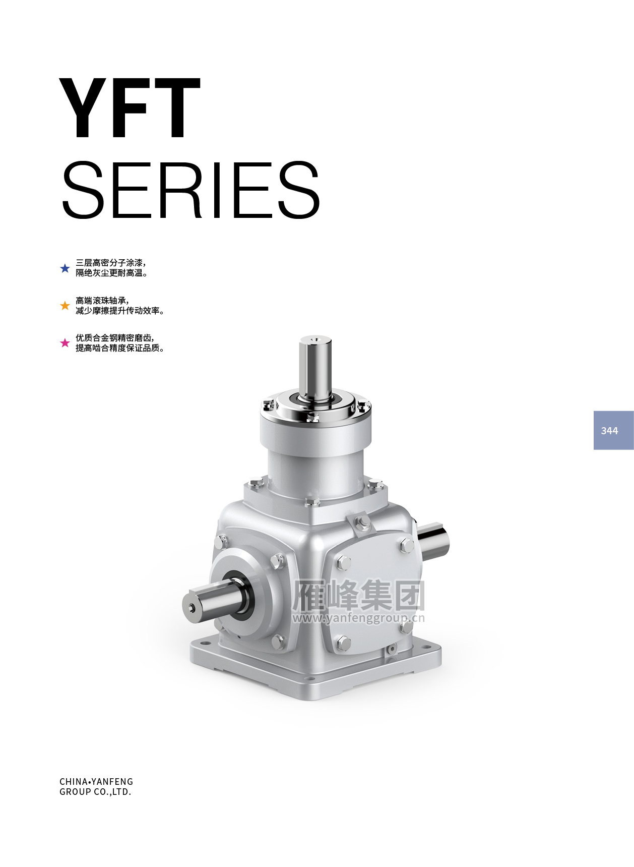
T series helical cone gearbox
Compact spiral bevel gearbox for 90-degree power transmission with high torque, low vibration and low noise.
Key data
- Frame sizes
- T2 – T25 (10 sizes)
- Ratios
- 1:1, 1.5:1, 2:1, 2.5:1, 3:1, 4:1, 5:1
- Unit weight
- 2 kg (T2) – 488 kg (T25); T4 10 kg, T6 21 kg, T7 32 kg, T8 49 kg, T10 78 kg, T12 124 kg, T16 188 kg, T20 297 kg
- Input speed range in tables
- 10 – 1450 r/min
- Rated output torque (MN2), 1:1 at 1450 r/min
- approx. 11.6 N·m (T2) to approx. 2274 N·m (T20); T25 approx. 3499 N·m at 870 r/min
- Rated output torque (MN2), max at low speed
- up to approx. 5713 N·m (T25, 1:1, 10 r/min)
- Rated input power (PN1)
- from approx. 0.01 kW up to roughly 335 kW (largest sizes at high speed; figure partly obscured)
- Service factor
- 1.00 – 2.00 depending on load type (uniform / moderate shock / heavy shock) and daily hours (≤2, 2–10, 10–24); bracketed values apply when starts/stops exceed 10 per hour
- Model designation example
- YF T 12 2:1 D-LR B3
Overview
The YFT series is a spiral (helical) bevel gear steering box: a right-angle gearbox that redirects rotation through 90 degrees. The catalogue describes it as delivering large transmission force, being suitable for both forward and reverse rotation, and running with low vibration and low noise. It is offered in ten frame sizes from T2 to T25, with unit weights ranging from 2 kg (T2) to 488 kg (T25).
Construction is a cast square housing with removable end covers on each face, a pair of spiral bevel gears (pinion and crown wheel) mounted on shafts supported by rolling bearings, with lip oil seals, bearing housings, shim rings, flat keys and a breather plug. The exploded view lists about 40 parts. The cover highlights a three-layer high-density polymer paint finish that keeps out dust and withstands high temperature, high-grade ball bearings that reduce friction and raise transmission efficiency, and gears made from premium alloy steel with precision grinding for accurate meshing.
Model designation follows the pattern YF T 12 2:1 D-LR B3, i.e. spiral bevel gear unit, size, ratio, shaft arrangement and mounting position. Standard ratios are 1:1, 1.5:1, 2:1, 2.5:1, 3:1, 4:1 and 5:1, and the same box can be used to reduce or increase speed depending on which shaft is driven. Shaft arrangements cover two-way (I-LR, I-L, I-R, I-U, I-D, I-UD, U-LR, D-LR and their -O reversed-rotation variants) and three-way / four-way layouts (I-I-LR, I-I-UD, U-D-LR and variants), and mounting positions B3, B6, B7, B8, V5 and V6 are shown.
The selection pages give a service-factor table by load type (uniform, moderate shock, heavy shock) and daily operating hours, plus a worked example of several boxes driven in series, where the box nearest the motor must carry the torque of all downstream boxes. Typical use is anywhere a right-angle drive or multi-output shaft line is needed, such as conveyor lines and screw-jack lifting systems.
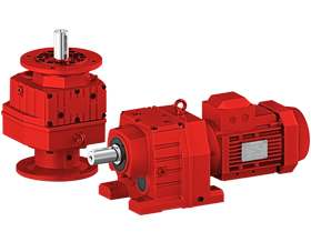
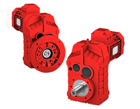
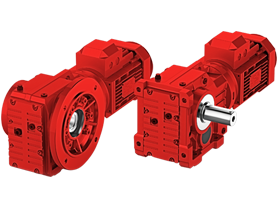
More Yanfeng gear units
Get a selection and price for the YFT series
Send us your bag size, output target and raw material and we will propose a complete line, or ask for a price and delivery time for a single machine. We answer in English; Arabic-speaking agents are available on request.